GAGGIONE’s Fresnel lenses LLF200 and LLF300 are designed for the traffic signal lighting market.
These fresnel lenses are specifically designed to ensure good visibility, safety, and durability. By simply adjusting the LED position beneath the lens, both angular distribution of luminous intensity requirements can be met: Type E (Extra Wide) and Type W (Wide) according to EN 12368.
Type W and Type E distributions support clear signal recognition over wide viewing angles.
The Type W distribution provides broad, reliable signal visibility across a wide field of view, supporting clear recognition in typical urban and road-intersection environments.
The Type E distribution extends signal visibility over a larger angular field, helping road users recognize the signal clearly even at short distances or from wider approach angles.
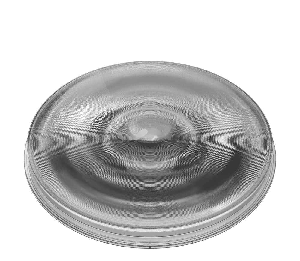
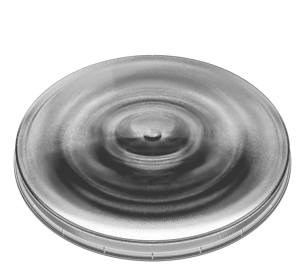
One side of the optical element incorporates a Fresnel lens, while the other side features a diffusive surface composed of an array of microlenses.
The focal length is 82 mm. The LED must be positioned in the focal plane.
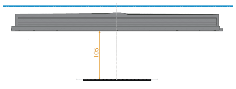
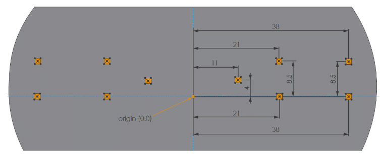
The following drawing illustrates the general mechanical configuration required for the LLF200 and LLF300, applicable to both Type W and Type E beam distributions.
The differences between Type W and Type E configurations lie in the LED arrangement on the PCB and the diffusion angle of the cover.
The PCB is placed such that the emitting surfaces of the LED are at the Fresnel lens focal plane, which means 105 mm below its mechanical flange.
The cover containing the diffusing surface has to be placed as close as possible to the Fresnel lens, preferably not further than 20 mm from it.
The side of the cover containing the micro-lenses has to be placed towards the LED.
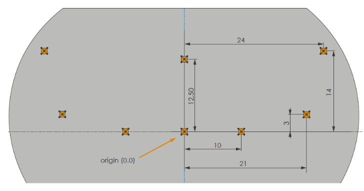
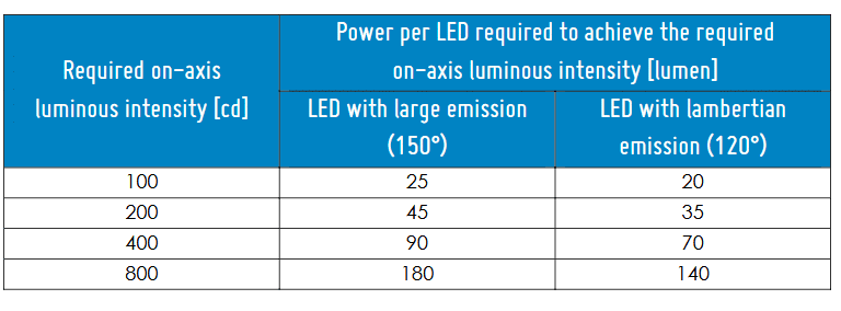
Traffic light type W
The dimensions refer to the center of the emitting surfaces of the LED.
This LED configuration needs a cover made of micro-lenses having an NA of 0.15, corresponding to a diffusing angle of +/-8.5 deg.
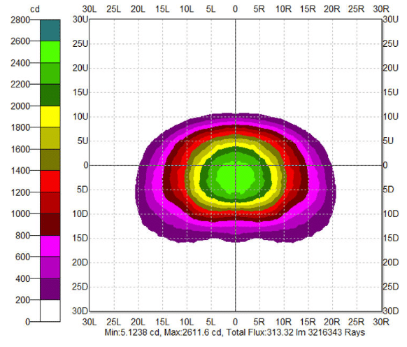
Here is the intensity diagram for a 1mm² domed LED, at any of the colors, assuming each of the LED emits 100 lumen:
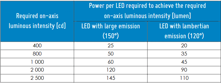
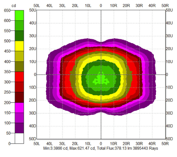
Traffic light type E
The dimensions refer to the center of the emitting surfaces of the LED.
This LED configuration needs a cover made of micro-lenses having an NA of 0.34, corresponding to a diffusing angle of +/-20 deg.
Here is the intensity diagram for a 1mm² domed LED, at any of the colors, assuming each of the LED emits 100 lumen:
Material and mechanics
These collimators are manufactured with Shore 70 silicone. When coupling multiple collimators together, it is recommended to keep a 1 mm to 2 mm gap between collimators to comply with the thermal expansion of the material : 27.5 x 10⁻⁵ cm/cm/°C. We recommend to glue the collimator feet to the PCB after assembly using silicone glue. The compatibility between the selected glue and the LED material has to be confirmed by the LED manufacturer to avoid any unwanted chemical interaction. We do not recommend to cut the collimator feet to match the exact LED focus point. Even if manufactured in a soft material, it will not be possible to have an accurate machining of the parts to ensure a proper alignement of the part on the PCB. For information, same PCB design and LED focus point adaptation will apply for both references.
LED spacing
To ensure a proper light uniformity, we recommend a 12 to 32 LED configuration per collimator. The proper pitch will depend on the LED beam angle and power.
We recommend using : • 12 to 24 LED per collimator for High power LED. • 18 to 32 LED per collimator for 5630 or 3030 midpower LED.
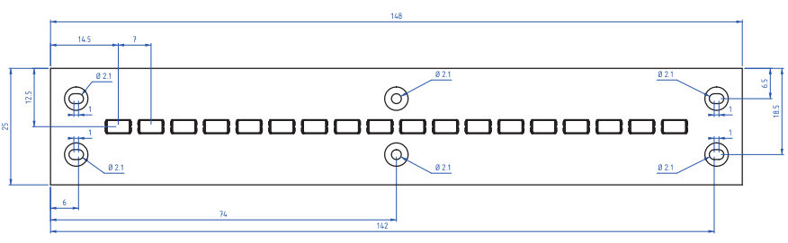
PCB drawing examples
18x Midpower 5630
STAY TUNED TO BE INFORMED ABOUT OUR NEW HIGHLIGHTS.