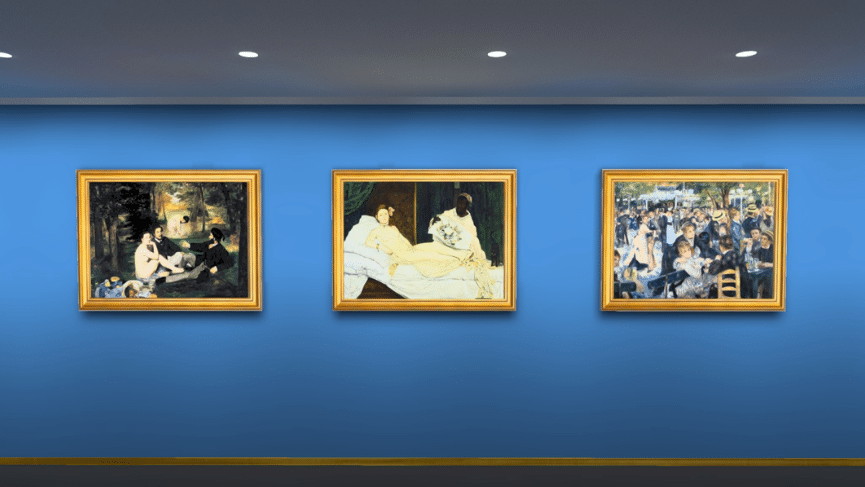
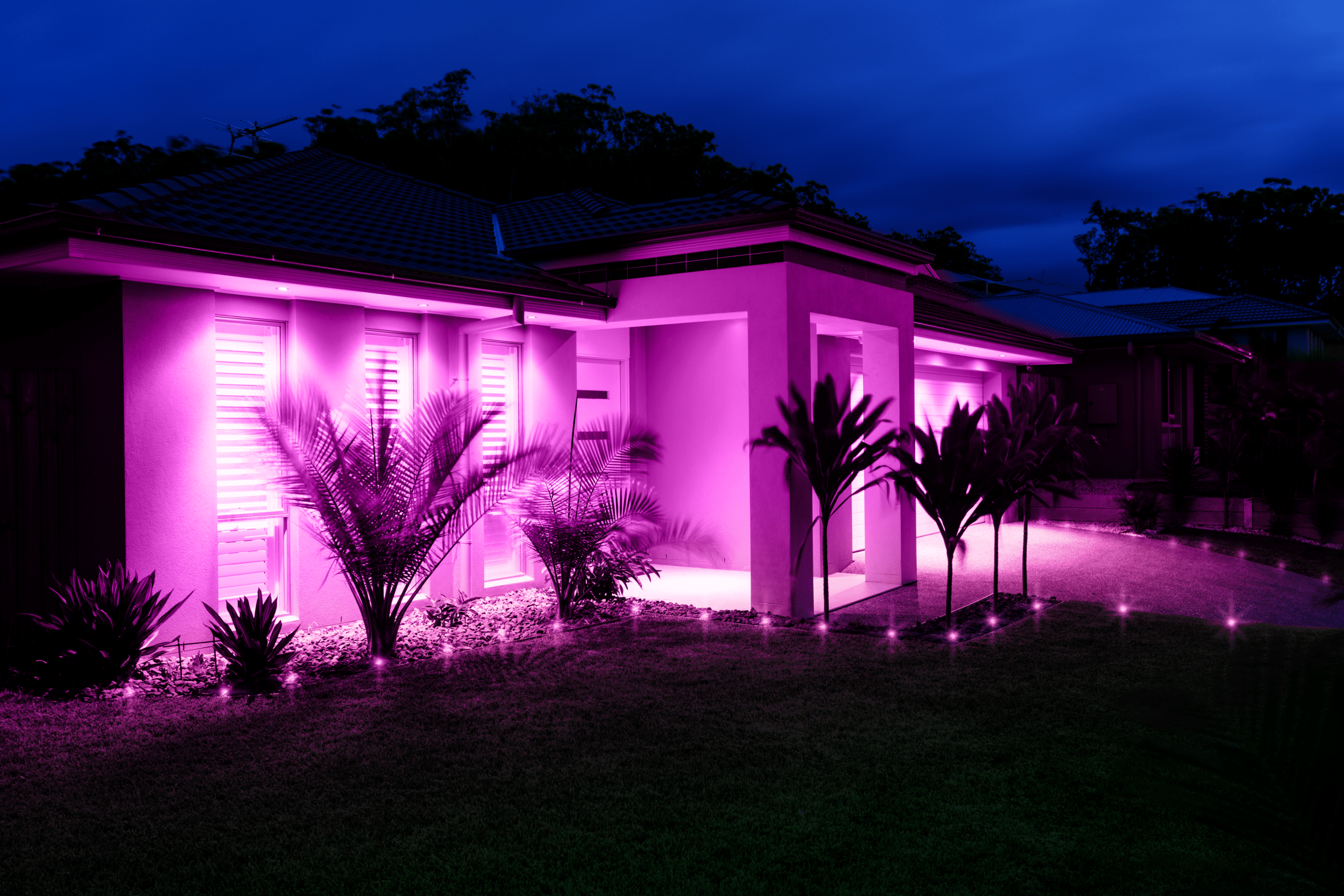
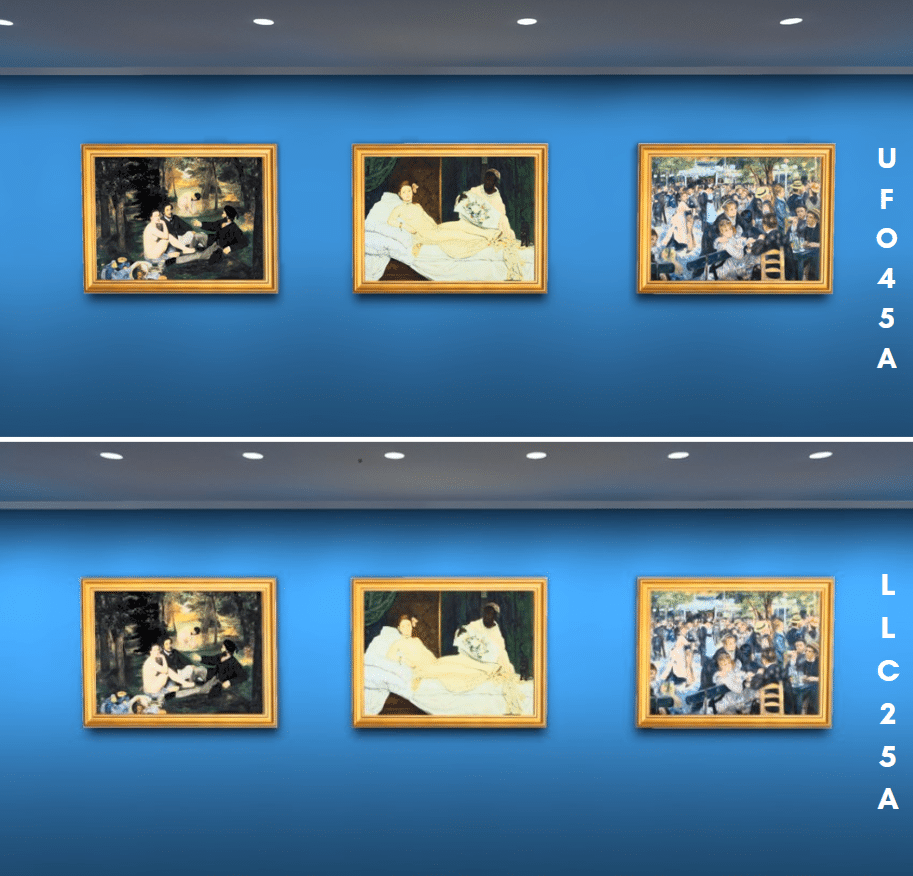
UFO45A simulation – Excellent light distribution on the wall, starting right from the beginning of the wall.
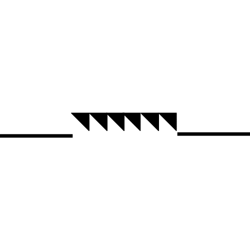
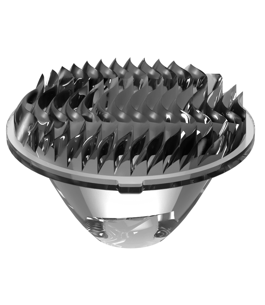
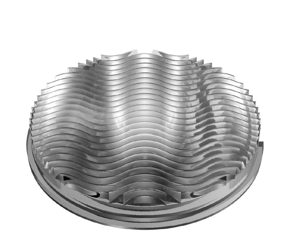
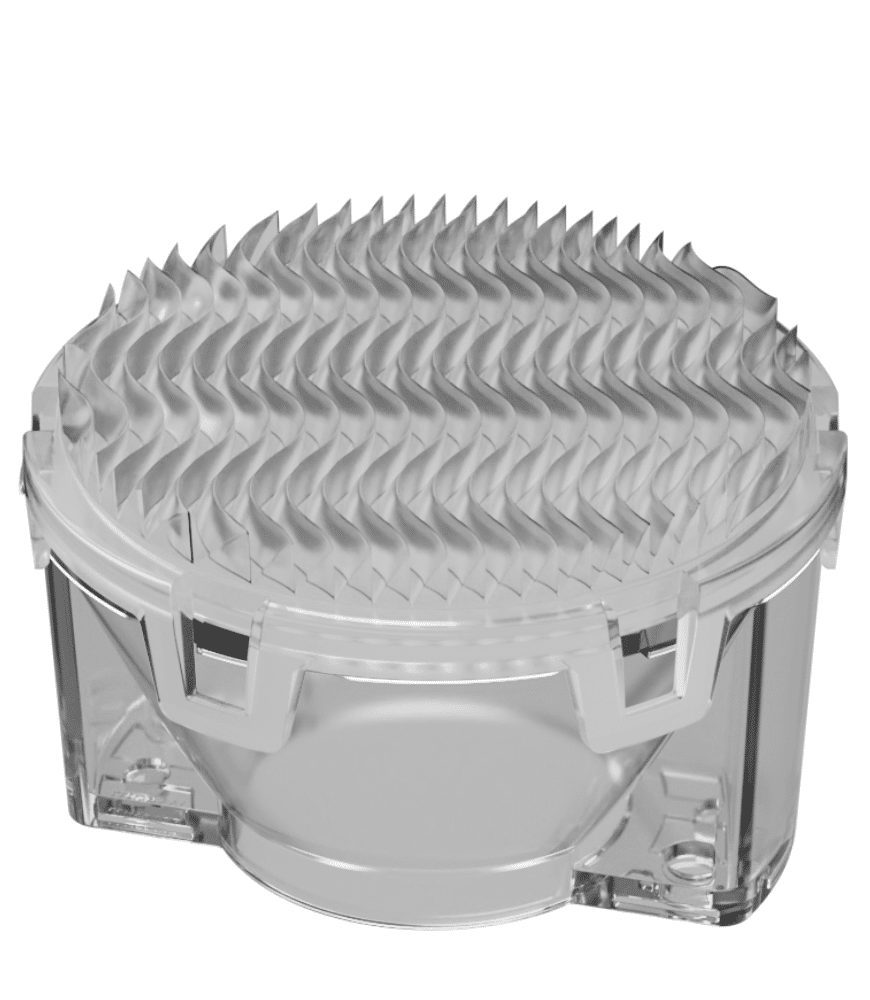
Rectangular beam
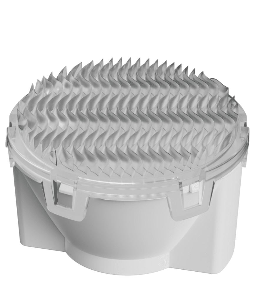
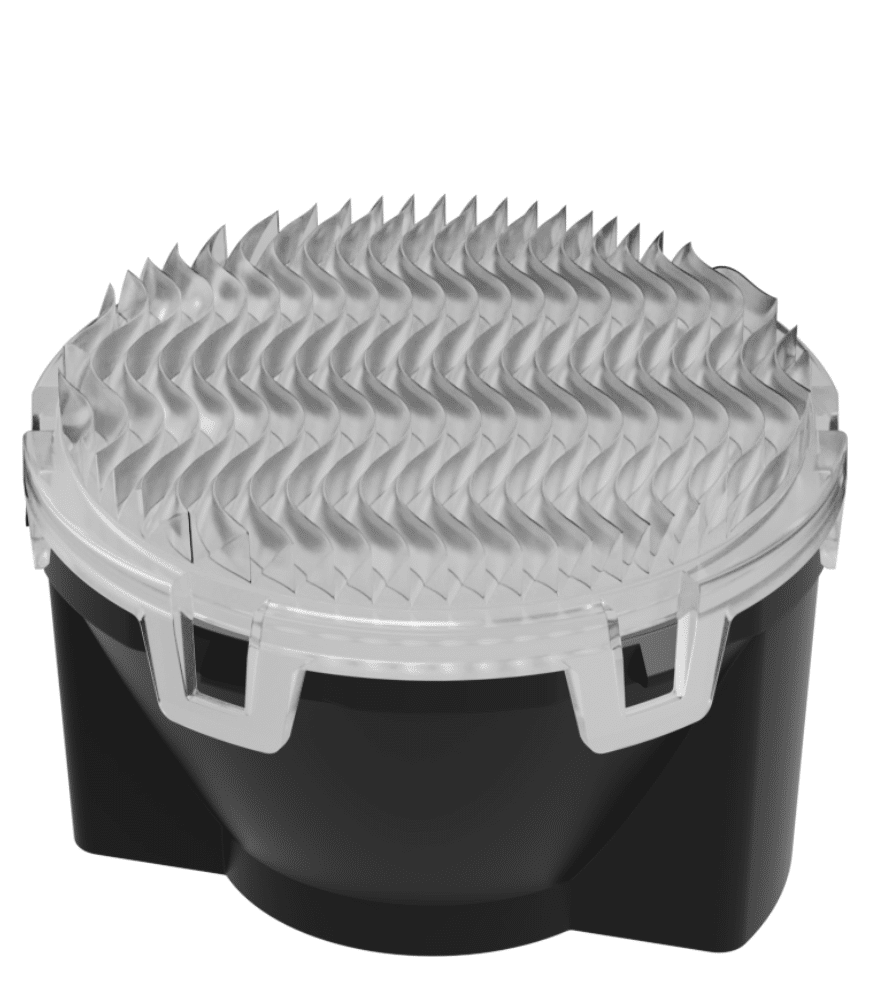
Recessed optic
Patented
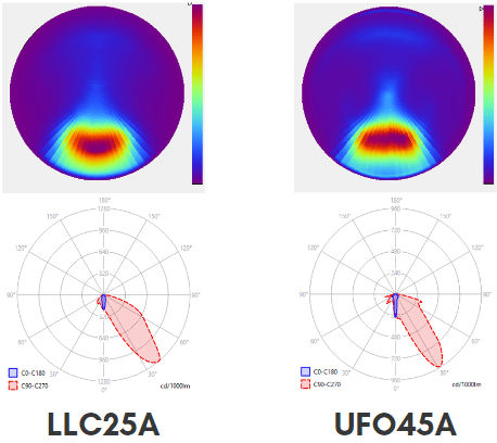
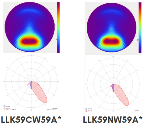
Photometry
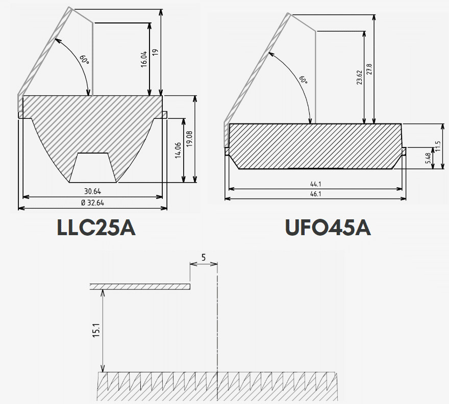
LLC25A
LOR front (wall) - 77.6%
Intensity peak front - 1279 cd/klm
LED : Cree – Ref : XHP35B HI (flat top)
UFO45A
LOR front (wall) - 76.9 %
Intensity peak front - 1130 cd/klm
LED : Citizen – Ref : CLU702
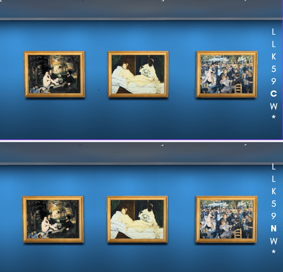
LLK59CW59A*
LOR front (wall) - 82%
Intensity peak front - 953 cd/klm
LED : OSRAM Ref : OSTAR STAGE S2WN
LLK59NW59A*
LOR front (wall) - 81%
Intensity peak front - 1026 cd/klm
LED : OSRAM Ref : OSTAR STAGE S2WN
Integration
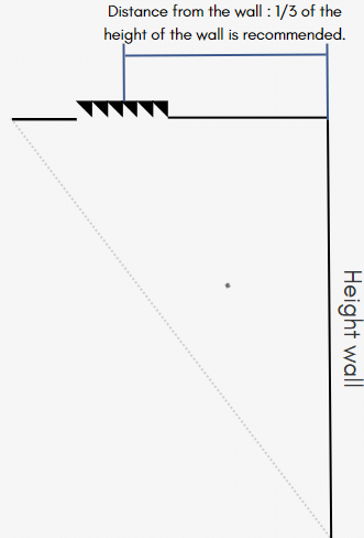
For the light to start as close to the wall as possible from the ceiling, the ideal distance from the wall is 1 meter.
UFO45A, LLK59NW59A* & LLK59CW59A*
The spacing of the luminaires should be equal or up to 1.2x to the distance from the wall.
LLC25A
The spacing of the luminaires should be equal or up to 0.6x to the distance from the wall.
Installation
UFO45A
LED : Citizen – Ref : CLU702 • 1300 lm per LED with 4 x UFO45A • Projection at 1 m from the wall • Spacing – 1.2 meter • Wall height – 2.6 meters
LLC25A
LED : Cree – Ref : XHP35B HI (flat top) • 800lm per LED with 6 x LLC25A • Projection at 1 m from the wall • Spacing – 60 cm • Wall height – 2.6 m
LLK59CW59A*
LED : OSRAM Ref : OSTAR STAGE S2WN • 800 lm per LED with 4 x LLK59CW59A* • Projection at 1 m from the wall • Spacing – 1.2 meter • Wall height – 2.8 meters
LLK59NW59A*
LED : OSRAM Ref : OSTAR STAGE S2WN • 800lm per LED with 6 x LLK59NW59A* • Projection at 1 m from the wall • Spacing – 1.2 meter • Wall height – 2.8 meters
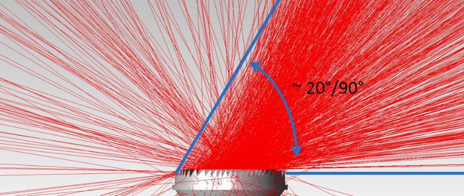
Focus on backlight
Even if the optical system is extremely well designed, there may be some unwanted light coming out of the optic. This light are rings around the main beam and they are not intended to the design, but the effect is inevitable with the highest intensity beams.
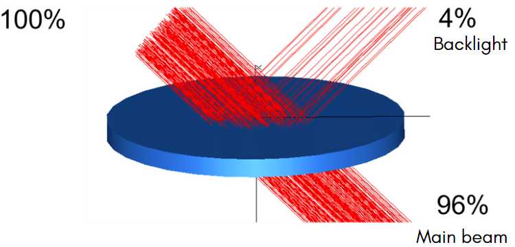
When light reaches an optical surface that separates two transparent materials, like plastic and air, around 96% of the light is transmitted and around 4% is reflected. This physical phenomenon is known as« Fresnel losses » and it happenseach time the light travels through a transparent surface. The asymetrical lenses LLC25A and UFO45A are bonded to this physical phenomenon and 4% of the incident light is reflected onto the asymetrical optical structure instead of being transmitted. This reflected light is what creates the backlight.
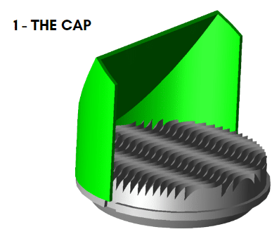
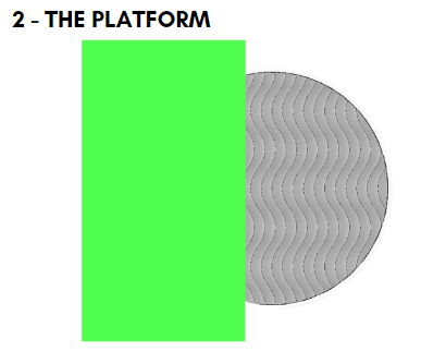
How to avoid it ?
To make this backlight disappear, we have created two concepts.