

Reading time : 7 minutes
Last update : September, 2025
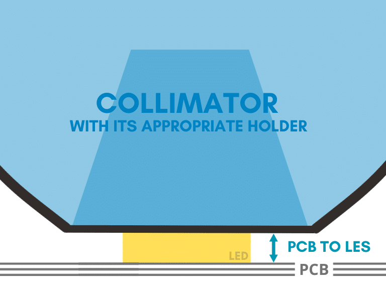
What is the PCB to LES distance / Focal point ?
The PCB to LES distance refers to the vertical distance between the Printed Circuit Board (PCB) on which the LED is mounted and the Light Emitting Surface (LES) of the LED. The LES is the point or area on the LED package where the light is actually emitted. This distance is a key mechanical parameter, as it defines the optical origin of the light source relative to the board. The definition of PCB to LES is especially important in systems where precise light positioning and direction are required, such as in optical systems with lenses.
Why do we need to know the distance PCB to LES ?
The Light Emitting Surface (LES) must coincide with the optical system focal point for optimal performances. So, understanding the distance from the PCB to the LES (Light Emitting Surface) is essential for accurate optical and mechanical design when working with LEDs. This measurement directly impacts optical alignment, especially in applications involving lenses, reflectors, or light guides. If the PCB-to-LES distance is incorrect or unknown, it can lead to poor light performance, inefficiency, homogeneity issues, or even mechanical integration issues. Knowing this value allows designers to properly position the LED in their system to achieve optimal light output and beam shape. In short, knowing the PCB to LES distance is a small detail that has a big impact on the overall performance and reliability of your LED-based product.
How to get the PCB to LES distance ?
When designing with LEDs, one of the most frequently asked questions is: How to get the PCB to LES distance? This crucial measurement—distance from the PCB to the Light Emitting Surface (LES)—is determined entirely by the LED itself.
To find this information, the first step is to download the LED datasheet provided by the manufacturer.
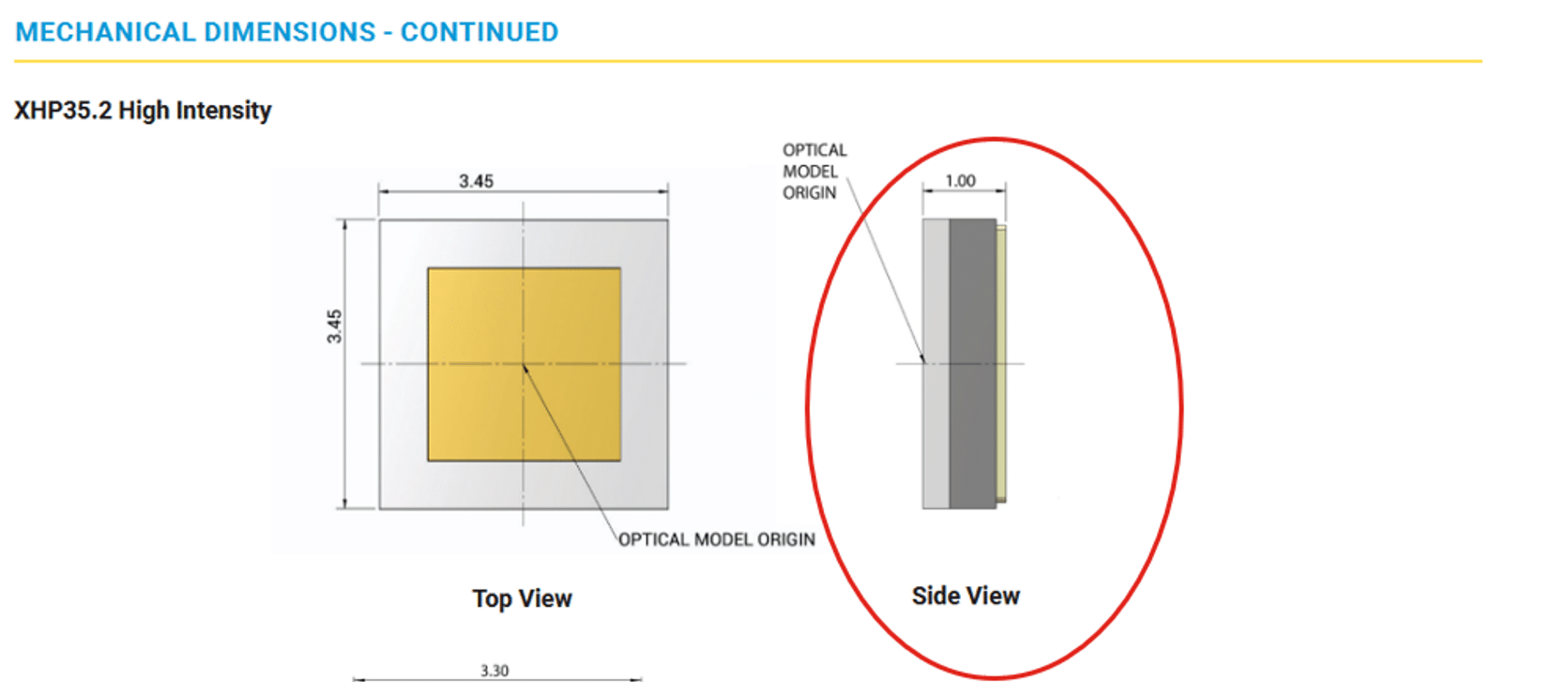
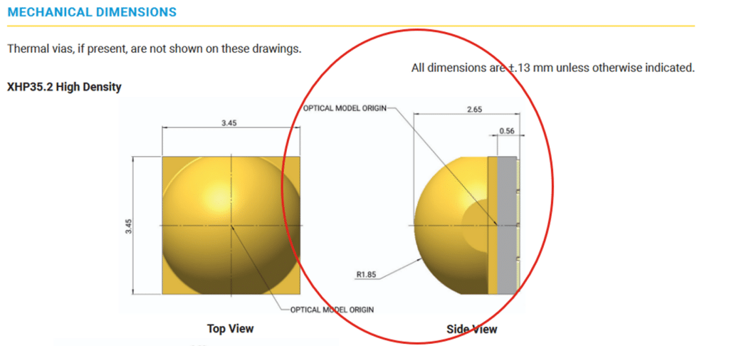
Once you have the datasheet, navigate to the section detailing the LED mechanical design. A well-documented datasheet typically includes the PCB-to-LES distance as part of the dimensional drawings.
Illustrative examples of a datasheet:
However, in some cases, this key detail might be vague or even missing altogether.
So what should you do if the datasheet doesn’t provide it?
1. General case – Rule of thumbs
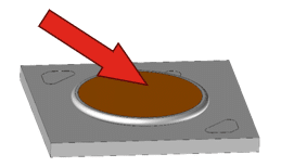
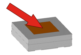
- For COBs : the LES is on top of the LED
- For flat top LEDs : the LES is on top of the LED
- For domed LEDs : the LES is at the curvature center of the dome
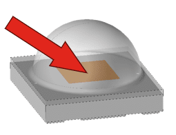
- àBe careful for some LED references : refer to the _info.pdf provided by the manufacturer, the LES may not be at the curvature center of the dome.
2. Particular cases
Some manufacturers provide comprehensive information about the PCB-to-LES distance, but it is hidden.
In that case, here are the steps you can follow to find this information:
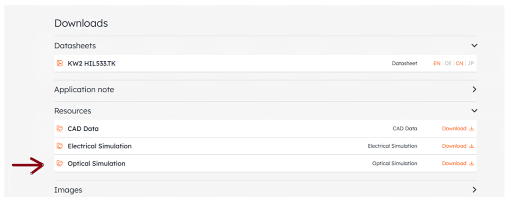
- 1. Start by downloading the LED ray file from the manufacturer’s website. This is typically a large ZIP file—often over 100MB. Most suppliers offer the ray file in different formats; for optical simulations, choose either the TracePro or LightTools format, depending on the software you’re using.
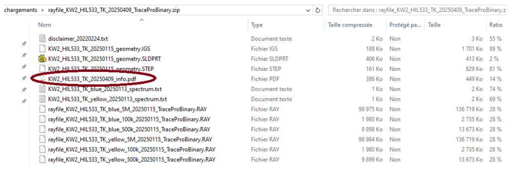
2. Open the …_info.pdf file in the ZIP file.
3. Once you’ve opened the ray file documentation, here’s what to look for:
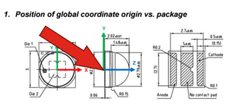
On the first page, you’ll usually find a diagram showing the origin of the LED package. In this case, the origin is located directly on the PCB, which is not always true—sometimes it might be defined elsewhere, depending on the LED design.
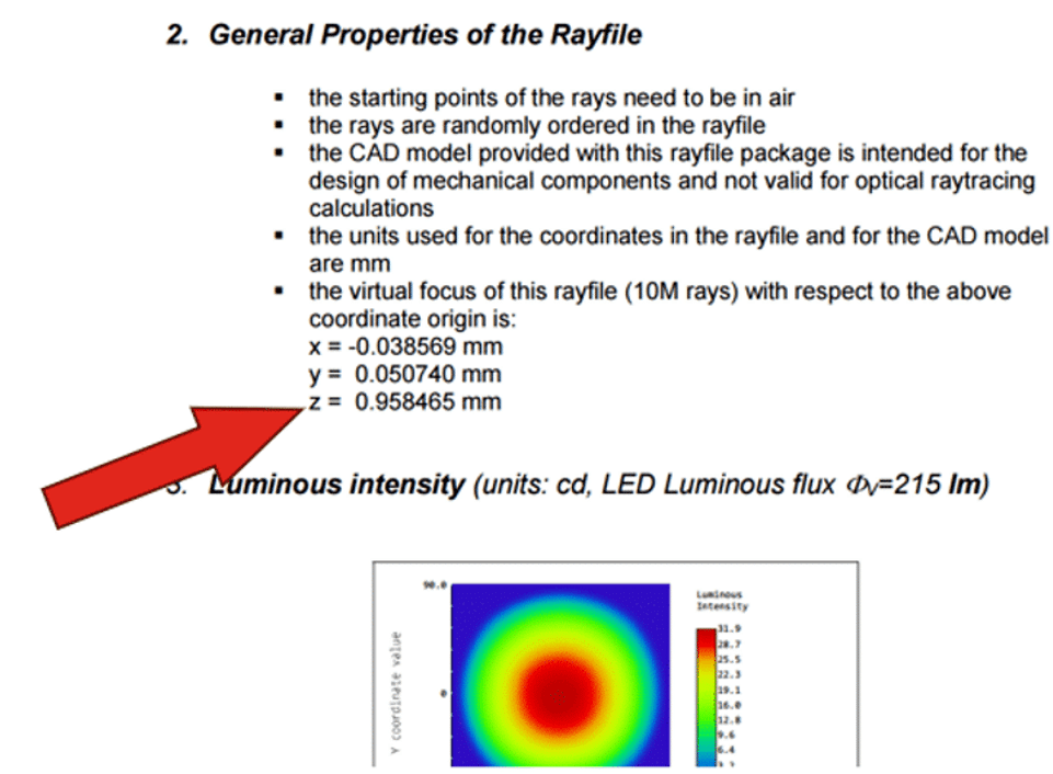
4. Then, moving to the second page, you should find the coordinates for the “virtual focus”, which represents the Light Emitting Surface (LES). In our example, it’s located at 958465 mm from the origin.
à With these two pieces of information, we can now easily calculate the PCB-to-LES distance: it’s simply 0.958465 mm in this case.
Optimizing optical alignment: Don’t overlook the holder
Now you know how to find this key information for your LED project design. Keep in mind, though, that other factors can also play a crucial role in the success of your optical setup. One common example is the integration of a holder, which can significantly impact the optimal focus positioning of your collimator. If you’re working on precise optical alignment, we highly recommend checking out the following blog post for further insights: HERE.